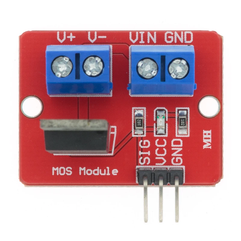
It's this one:
Image may be NSFW.
Clik here to view.
V+ and V- are connected to my PWM fan (pin 1 and 2)
Vin and GND are connected to the 12V power supply.
PIN HEADER
SIG is connected to GPIO12 (pin number 32) on the Raspberry.
VCC not used
GND is connected GND (pin number 34) on the Raspberry.
So the 4th pin on my fan is not connected to anything. This is the PWM signal, but i don't know where to connect it.
Image may be NSFW.
Clik here to view.

V+ and V- are connected to my PWM fan (pin 1 and 2)
Vin and GND are connected to the 12V power supply.
PIN HEADER
SIG is connected to GPIO12 (pin number 32) on the Raspberry.
VCC not used
GND is connected GND (pin number 34) on the Raspberry.
So the 4th pin on my fan is not connected to anything. This is the PWM signal, but i don't know where to connect it.
Statistics: Posted by woostendorp — Sat Sep 14, 2024 7:17 am
